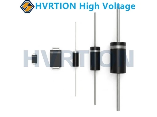
1. Using an analog multimeter: Set the multimeter to the "R×10k" range. Because high-voltage diodes have high withstand voltage, this range provides a higher test voltage. Connect the red and black probes to the two terminals of the diode respectively. Under normal conditions, during forward measurement (black probe to positive, red probe to negative), the multimeter pointer will swing slightly, indicating some conduction resistance. During reverse measurement, the pointer should remain almost stationary, and the resistance should be close to infinity. If the forward and reverse resistances are both zero or infinite, or similar, the diode may be damaged.
2. Using a digital multimeter: Set the digital multimeter to the "Diode" measurement range. Connect the red probe to the positive terminal of the diode and the black probe to the negative terminal. Normally, the multimeter will display the forward voltage drop of the diode. Generally, the forward voltage drop of a silicon diode is around 0.5-0.7V, and that of a germanium diode is around 0.2-0.3V. During reverse measurement, the multimeter should display "1" or an overflow symbol, indicating that the diode is cut off and the resistance is very high. If the measurement results do not conform to the above conditions, the diode may be faulty.
3. Circuit Testing: If a high-voltage diode is suspected of being damaged in the circuit, first disconnect and discharge the relevant circuit to ensure safety. Then measure its forward and reverse resistance in the circuit and compare it with the normal values. However, note that other components in the circuit may affect the measurement results. If necessary, the diode should be desoldered from the circuit for independent measurement to accurately determine its condition.